

Theory and experiment of direction finding
James Clerk Maxwell’s mathematical theory of 1873 had predicted that electromagnetic disturbances should propagate through space at the speed of light and should exhibit the wave-like characteristics. This time many were seeking experimental evidence to establish the equivalence of light and electromagnetic propagation. After that, in 1887 Heinrich Hertz as professor of physics at Karlsruhe Polytechnic designed a brilliant set of experiments tested Maxwell’s hypothesis.
Practical applications
Hertz with his discovery of the directional properties of radio waves launched the field of radio direction finding in 1888. Since than we use this characteristic of the radio:
- firstly, to determine our own location against a known transmitter (radio navigation) or
- secondly, we know our own position and like to determine the location of the unknown transmitter (radio reconnaissance)
Military users soon recognized the value of additional tactical and strategical informations and WW I and WW II brought us triumphant advances of RDF in all aspects. RDF is part of passive EW (Electronic Warfare), the targeted station tries to radiate information in a narrow beam to its addressee, thus avoiding detection by RDF.
In addition, non-professional users as well can profit from RDF, if they opt for a suitable system. This short overview shows aspects of professional RDF and hopefully might give some advice to the inclined hobbyist.
Lot of practical equipment is based on the directional property of radio waves and direction finding.
Direction Finding Receivers
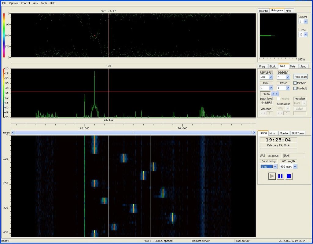
Sagax Communications proudly announce that radio direction finding (DF) functionality is available in their search intercept and monitoring collecting receivers too. The internal direction finding processor develop the incoming direction of all spectral components of the bandwidth under reception. It is displayed on special type of graph as azimuth angle (bearing) versus frequency.
In the channelized monitoring receiver the bearing/azimuth angle is associated to the channel signal and one angle is displayed in a classical compass rose display.


Direction finding antenna
For being able to determine the direction of the incident wave you have to use a special antenna system. Sagax Communications offers several antenna compatible with the receivers for the most important frequency bands.
Sagax Communications – Always on Target
Follow us on your favourite social media